SAR LMS GWR

SAR LMS GWR
SAR "Commercial Street" - LMS "Wellingford & Bakewell Bridge Railway" - GWR "Porthminster" - Port Dock Station

Friday, 19 June 2015

Great Moor Street - Minories

Great Moor Street in OO scale in all its old world splendour.
An overview of the station canopies. An Ex Midland Flatiron 0-6-2T waits in
Platform 3 with some Ex LNWR stock.
As a lad of a young age I looked starry eyed at a unique hinged baseboard idea that I had seen in my edition of “The Railway Modeller Book of 60 plans for Small Locations”. I would like to build that one day….the time had come and so it was done. This fold up railway using a space of 7ft x 1tf in size was known as the “Minories”. Consisting of a terminus station at one end and a specially set out track design at the other end, it offered train operations like no other. It was a signature piece by CJ Freezer no less, and learning over the years that his designs were held in high regard, I give it a go. The terminus station has the high surrounding walls each side of the whole station and a road bridge straddling the station platforms concealing a pair of hinges. This allows the two baseboards to be folded over on each other for transport or storage. To make the terminus operable, a fiddle yard would then be attached at the station throat concealed under another road bridge leading into a hidden fiddle yard, which would be bolted on to the Minories.
A view under the canopies of Great Moor Street. I think this photo captures the
right atmosphere which was what I was striving for here, that maze of frames
and elegant styling of the steam days.
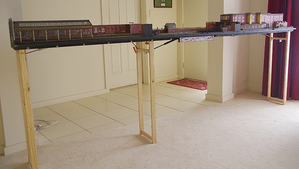
My thoughts were to have a fiddle yard that was permanently attached to the station throat via another set of hinges; the whole layout would fold up on itself without having separate baseboards. Making use of a large warehouse building as a means of hiding the fiddle yard, and using block sections at the end of each siding, this allows the operator to run trains from the terminus to the fiddle yard and back without touching/handling any engines or rolling stock. Under-track magnets would be located at appropriate positions around the layout to allow hands free shunting using Kadee couplers.
The layout plan which shows the three 1065mm modules that fold over
each other - all permanently fixed together with hinges.
The view of the coal staithes and signal box. All the points are switched
using a simple push-rod system attached to a slide switch which changes the
polarity of the attached point. The mini control panel can just be seen
below the front ledge.
Timber baseboards were made using 6mm MDF fixed to 42 x 19mm pine frames, with 6mm MDF used for the station end and side walls, warehouse walls and road bridges. Self-supporting legs extend from under each baseboard section and are kept open using gas struts. This makes for very rapid erecting and knockdown of the layout. The warehouse takes its cues from the Ex Midland Railway Sandon & Canada Dock Goods station.
A view of the lift off bridge that covers the hinges fixed on either side on top
of the abutments. The bus on the bridge is of a local bus line with
"Plodder Lane" written on the destination boards - appropriate for the area.
Two Metcalfe Models Warehouse Kits were grafted together with scratch built hoist towers to achieve the result. The terminus was modelled on the Ex LNWR Bolton Great Moor Street station in Greater Manchester. A number of images exist on the World Wide Web and so I collected them as reference for scratchbuilding the station with its red brick architecture. The station canopy was scratch built from copper wire, basswood and styrene, with 1.5mm acrylic sheet used to represent the glass roofing and side wall panels. Each of the trusses in the canopy were made on a jig with soldered copper wire. This ensured each truss was the same as the next. Station walls with their arched panel design were made from balsawood covered with Metcalfe Models brick paper. The signal Box was a Metcalfe Models Kit suitably re-detailed to more faithfully represent the standard LNWR design. Platforms are adorned with Ratio Kit LNWR signals, Dapol book stalls and Langley Models kit built gas lamps. Mikes Models LNWR water columns and scratch built coal staithes stand opposite the signal box.
A 4F enters station throat from the hidden sidings, heading for the goods
road in the station to be reversed into the sidings after the 0-8-4T has
completed its shunting moves. The water tank structure is removable to enable
the canopies to clear that area when the layout is folded up.
The large warehouse hides the four storage roads. The wagon turntable is located on the piece of baseboard
that sticks further out. The furniture factory siding comes right to the end of the layout.
Wagon turntables were a common sight in and around many large goods sheds, so I incorporated one along the front sidings of the warehouse. I used an Atlas Track 90 degree crossover cut down to size and secured with a central pivot screw. It sits in a scribed balsawood deck surround which represents the timber planking commonly used to cover the drive mechanisms for the capstan rope tow system. Although the turntable is for static appearance only, it gives the scene purpose and access to the furniture company siding at the end.
For more photos, a Plan of the Month feature was published in the April 2015 edition of Railway Modeller of Great Moor Street.


The layout folded up and placed in the back seat of my car
ready for transport to a convention. Seat belts are used to restrain
in case of an accident.
This shot shows the layout semi-folded. The two station modules are folded on top of each other 
with the hinges in the bridge abutments (at floor level) and the warehouse hidden sidings module hinged
at the throat of the station (seen at the top) The sets of legs are hinged and fold into each module and are
held open by gas struts. This makes for very fast erecting and folding up times.  All the legs, power supply,
on board sound system and control panel are permanently fixed so the whole layout is self contained.
This shot shows the layout erected before adding the curtains and
rolling-stock. The control panel can be seen in the centre.
A side on view looking under the side glazed wall of the canopies.

Friday, 13 June 2014

My future Virginian Railway

I have decided to build a model switching layout based on the Virginian Railway. Details to come!
A Proto 2000 model of a USE Class for the VGN.

Wellingford & Bakewell Bridge Railway - Plan

At the recent Adelaide Model Railway Show 2014, I was asked a number of times from members of the public weather I had a drawing of my LMS layout I had on display. I didn't have any copies available so here is the plan of the layout for those I indicated for reference to this blog.

Wellingford & Bakewell Bridge Railway 
I will add some more photos later. There are a number of YouTube clips of the layout available if you search. I would recommend this clip done by a good friend of mine.

The photos below are of two stations, Wellingford, a name of my own making and modelled in the LMS style. Bakewell Bridge is modelled closely on Bakewell with a few enhancements to fit the scene.

A local goods comes off the branch into Wellingford
while a coal train waits patiently.
Bakewell Bridge Station - an adaptation
of Bakewell Station in Derbyshire in the Midlands.

Friday, 23 May 2014

Loughhead Viaduct completed

Some twenty months after starting this layout project, the viaduct scene is mostly complete. Only a few small details remain, but my fears for creating the right feel and atmosphere were allayed when the sea waves were finally completed.  I struggled with the arrangement of the beach scene, having never modelled one before.  My first attempt at getting the sea water texture right was a failure. Not happy with it, I scrapped it off and re-applied the colouring of the sea floor and waves.   I think I have the desired effect, with waves and sea water made from clear silicone sealant. The waves were made by squeezing out a rib of sealant where you need the wave front, and teasing back toward the sea with a finger. For the larger wave I did this twice to gain some height at the wave front. The rough water effect behind the waves were then made by dabbing the finger up and down. You could feel the sticky effect as you did this and it left a rough surface much like very course sand paper. Once dry, some white acrylic paint was applied at the wave front, only on top and not at the front of the wave edge, drawing the brush back toward the sea leaving a fading appearance. Once dry the whole water area was given two coats of gloss clear acrylic varnish.
Sea water with the new wave coming in over the previous wave,
and the wet sand at the water line.
The fresh water outlet
and point in the land
 across the base
board join.
The viaduct traverses an estuary and a scene with rocks and a shallow area where the sea meets the fresh water was needed. Considerable thought was given about the way the sea and land contour at this point was to accommodate the join the base boards. To avoid a join in sea water, the land swings out to a point right at the join. This has worked out well in creating a nice small cove for the fresh water outlet, and conceals the join quite well.

To give the scene a little more interest, a small flock of seagulls were added.
Seagulls at the fresh water outlet. Rocks were made using kitty litter,
glued downand then washed with a sloppy brew of plaster and water.
Sand is local beach sand near where I live. 


As mentioned in the introduction to this project, (see the first post for Porthminster on how I acquired the viaduct) I have decided to name the viaduct after its builder. The Moping Branch Railway built by Kevin, was begun in the 1960s and he had built the viaduct into what was a South Australian Railways layout. Though the railways never used this type of viaduct in South Australia, he must have thought it ideal to incorporate it into the layout as it was an important link in the railways operations, linking two stations across a large dip in the landscape. Kev’s surname, Loughhead has that British, very Scottish ring to it actually, so I thought it would be most appropriate indeed. Some extra detail has been added to the viaduct to complete its authenticity.  A number of the larger viaducts in Cornwall had refuges mounted along the deck. A very useful source of detailed information was obtained from John Binding’s book, “Brunel’s Cornish Viaducts” which shows that a refuge for the maintenance men were built into the deck at two span intervals.
One of the four refuges added to the deck, shown before painting.
Also this viaduct has the type “B Class” timber fan construction, so there needed to be wrought iron tie rods mounted between the spans. I added these, made from spring steel and work hardened copper wire, all soldered together at the intercepting points, representing the cast iron intersection plates. Each tie rod end was supa-glued in place to give the final touch to this magnificent structure. The whole viaduct has a very rigid feel to it now. Reassuring, considering its “lightness” in appearance.
Showing the arrangement of the wrought iron tie rods and a completed refuge.
I hope you are as pleased with its appearance as I am. Shades of the viaduct at Pendon Museum no less!  I still do intend to visit England for the first time one day soon, and Pendon will be one place I need to see.
Looking from the derelict tin mine end of the layout.
Looking from the Porthminster terminus end of the layout.
I chose to model the tide out on the beaches.
I was going to originally include a Fisherman’s Hut half way down the path from Porthminster Station to the beach, but it wasn't going to fit well into scenery. I then settled on a scene on the far end of the beach under the viaduct. This turned out to be a very pleasing scene with fishing boats tethered to moorings on the beach. A couple of old photographs come to light during my research of St Ives of fishing boats all piled up on the beach in the 1910s and 1920s, before St Ives become extremely popular with holiday beach goers. As more and more people came to the beach in these early decades, the fishing fleet was being slowly reduced. So a token small amount of boats are portrayed here. The hut is one of the Hornby Skaledale offerings and is a wonderful building with its leaning chimneys. Jewellery chain strung through steel split pins provide the barrier. All of the rocks in the cliffs are made from carved Styrofoam.
The Fisherman's Hut nestled
under the viaduct.

The local fishermen surveying the sea
for a chance to get a catch!
The building sits on a stone plinth,
high enough to avoid the sea
waves in rough weather.

The next part of the project is Porthminster Station and its village..............the last part of the layout's construction. Till next post, happy modelling and enjoy!

Monday, 12 May 2014

The other tunnel gets attention!

The other end of Penwith Station has had the tunnel portal decorated and the under track access to the goods yard fitted out with bridge girders and stone walls.
Plastered in portal ready for the
underpass wall installation.
The retaining walls were all curved
so I used some double laminated
2mm cardboard to hold the shapes.
The landscape was then covered with polar fleece, the material pullovers or sweaters are made from. One side of the material is quite short shaven, the other has a longer "furry" look to it, which is the side I used to show. Its all glued down with PVA glue. Being a stretchy material it will pull over all types of undulating surfaces. Its then trimmed with a small pair of curved scissors along the profile edge.
What a difference some grasses, bushes and trees make here.
The bridge girders were scratch built from styrene of a typical design seen on the Great Western Railway. These were simply glued on to the 6mm MDF track bed.
The portal now requires the inside walls to be installed to complete.
The telegraph pole seen here is the last pole on the telegraph lines that come through Penwith Station. Above the portal there will be houses, so the communication lines need to pass through the tunnel. Therefore electric cable trunking was installed to this pole, down to the track side, and run into the tunnel. It would then come out the other end of the tunnel and up another telegraph pole and continue on to next signal box along the line.
Telegraph pole with cable trunking.
An update on the Viaduct side of the layout will be forthcoming shortly!

Monday, 14 April 2014

A Goods Shed for Penwith yard...

A large size of Goods Shed was needed for the loading track, but what to put there? Having built a Metcalfe Models red brick goods shed before for my Wellingford LMS layout, I supposed it would be a good idea to merge two together to get the six window/bay length.  Making the necessary modifications along the way to obtain a near enough looking model proved successful. The goods sheds used for reference were those of the style at Tetbury or Broadway to name a couple.
The two Metcalfe kits melded together with the office and weighbridge rooms attached at the end, all card used from the two kits. The only things added was a large sheet of Metcalfe slates for the massive roof and the upper skylights at each end. These window skylights were also typical of this design shed.
Adding the frame peices individually.
To make the skylight windows, I scanned a diagram of Tetbury Shed in a publication, scaled it to the right size for the model and printed it out on copier paper. Window panes were then individually cut out and the paper skeleton was then PVA glued to some clear shirt box lid. After fixing the windows to the model, the individual styrene frame pieces were glued in with PVA glue to complete.
The main line side of the Goods Shed with that unmistakable skylight window style.
A steel beam at each of the entrances was also added as per the design.
To finish, gutters and downpipes were strategically placed to cover joins in the card walls.

GWR water tanks & footbridge

Before painting.
This layout keeps putting up challenges. You know that saying – if you want it done, do it yourself. Not available as kits, these tanks had to be scratch built. This was the case where the water tanks were concerned. Commonly known as Brunel style tanks, I had a go at building them with a little trickery thrown in! The models mostly consisted of styrene, with the cast iron parts of the columns dressed with copper wire.  Research showed that there were many size tanks made but all had a similar styling with regard to the cast iron work. I needed one for Penwith Junction, and being  a main line station needed to be larger rather than smaller.
Applying the printed cast iron looped frames.


The difficult area was the cast iron looped frame directly under the tank. My solution was to draw up a colour image design on my PC and print it out on matte photo paper. Trimmed and glued on with a degree of weathering, it looks convincing.


While I was on the tank thing, I made up an all steel type to present to a friend who has helped me out with reference books, videos and photocopies of relevant material that I needed for the Porthminster project. He now has a nice matching set for his GWR main line station.


The tank was of the same style but with the all steel "I" beams. The two cranes are from the Ratio range, shortened slightly to sit on top of the passenger platforms, complete with fire devils. These combustion fires were used to help prevent water freezing the pipes when not in use between visiting engines during inclement weather.

Another item of purely Great Western style was the footbridge. I procured a kit from Scalelink, but I was somewhat confused by the instruction sheets and construction methods. I assembled it my way with a few modifications along the way. One being that it was to be wider than the kit instructed. Fortunately there was enough length in the etched brass lattice sheet supplied to account for this.
Also I added guttering and downpipes, plain ends to the canopy at the bottom of the steps and a few tweaks to the flimsy canopy frames to make them stronger.
Acombination  of styrene and brass works for me. Supaglue is the answer here. whatever it takes to achieve the result.


It worked out well and sits proudly across the platforms matching in with buildings as they were at Radley Station, which the buildings were modelled from.

The completed footbridge.
The layout is now starting to look more like a railway with curtains made and clipped on with press studs. A must for top presentation at Exhibitions. There is still another coat of Carriage Green to be applied around the fascia areas above the curtains.
Looking from junction end of Penwith Station.
Looking from the goods yard end of Penwith. The four doll signal gantry
sit proudly on the platform ramp. Another Scenecraft Signal box is
place opposite with accompanying point rodding and ground signals.
Till next time - good modelling!!!