SAR LMS GWR

SAR LMS GWR
SAR "Commercial Street" - LMS "Wellingford & Bakewell Bridge Railway" - GWR "Porthminster" - Port Dock Station

Friday, 6 November 2015

The Running Shed

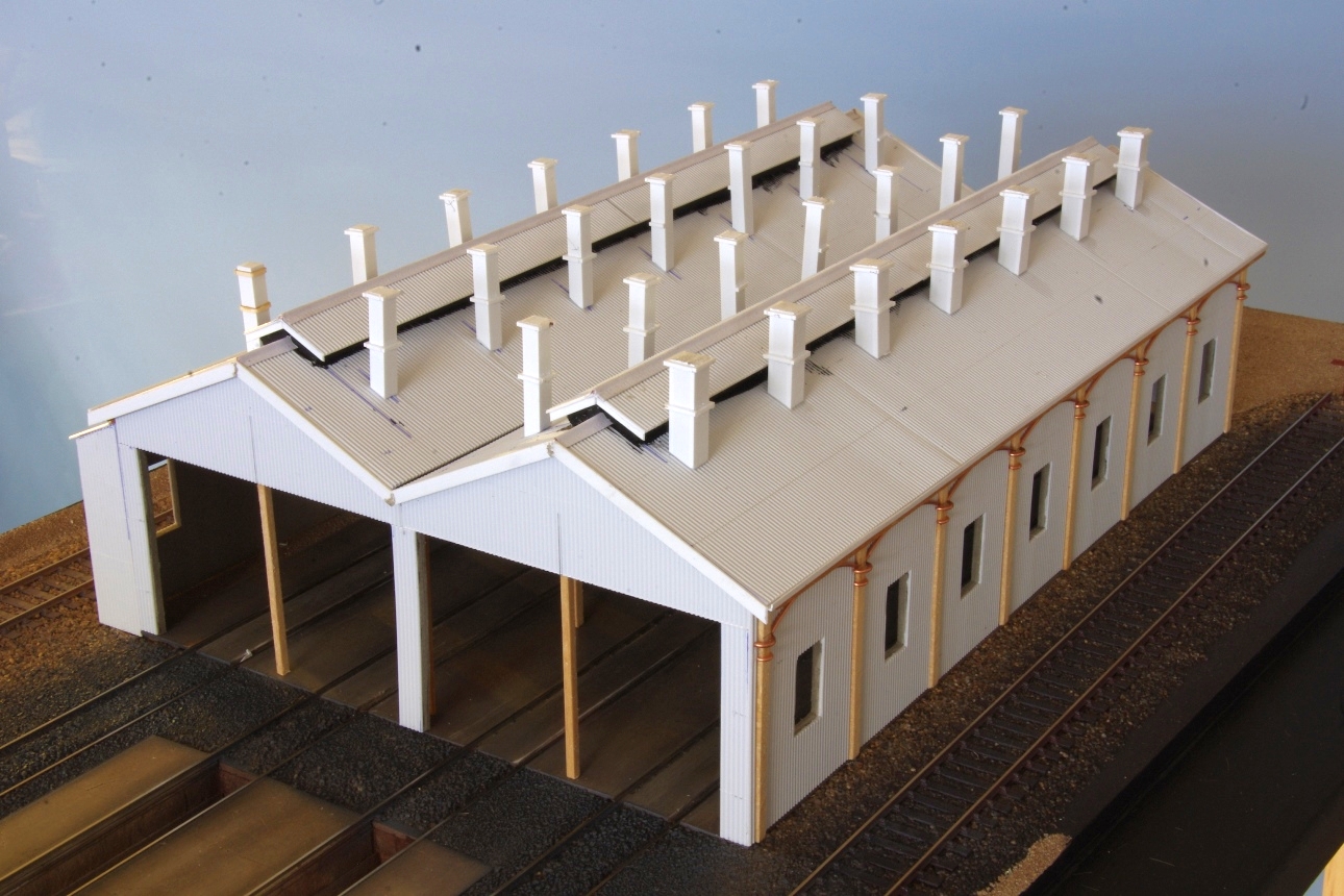
Some stage by stage shots of the running shed. Constructed from 2mm card. Keep in mind this is about half the length of the prototype....
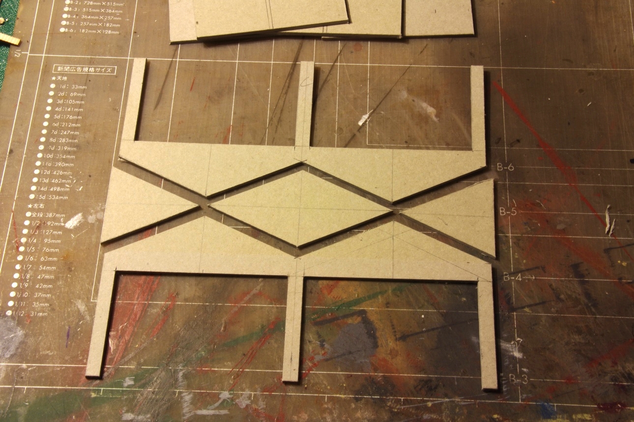
The ends cut out using a sharp knife.
The roof added and sat in place on
the shed floor to make sure it
was the right size.
Marked out sides with the windows cut out.


The shed shell completed ready for cladding.
The shell was then covered in corrugated iron styrene, timber woodshapes for the vertical posts and the decorations added. Copper wire for the side wall valances and individually made smoke chutes along the roof.
Where the posts intersected with the
arched valances - there was cast iron corbel.
To represent the corbel I filled between
the copper wire rings with PVA glue
and let it dry.


The roof has long ventilated gable caps so these were made
from styrene corrugated iron and glued on to balsa-wood strips
to create the gap under the vents.
The shed now ready for painting.
A coat of primer then a
coat of mid grey to represent the
colour of raw corrugated galvanized iron.
The shed now painted and weathered with powders.


With a couple of locos on shed - its starting to look good.
Last details to add are the windows and downpipes

The Signal Cabin....

I used a kit I bought from the US and modified it to look more like the one that used to be in the yard. I added corrugated iron to the roof instead of the tar tiles and shortened the base, but still keeping the lower floor window and door. This is a laser cut timber and card kit which I found to be very accurately cut and easy to assemble. 
The basic cabin put together with some of the bottom section shortened before assembly.
The kit that I used from the US.
The roof was ok to use but needed to be enlarged slightly,
Again I used styrene corrugated iron and copper wire with copier paper for the ridge capping.
The guttering I made using 1.5mm styrene angle iron, and a couple
of down pipes ready to go on after they  are painted.
Once painted in SAR colours of the era, I think it's quite convincing. Just need to put all those damned weeds in and around it now!
The completed signal cabin in place.

The station water crane

One of the water cranes for the station, which was not a common type for the South Australian Railways was situated at the end of the island platform. Made from plastic tube with a piece of copper wire inserted inside to hold the shape once the tube was bent. Some small steel washers were used to represent the cast pipe flanges (at the valve) and a hand brake wheel from the scrap box for the valve wheel.

The water column at the station
I made this crane from a Chupa Chupa
stick, some styrene and some copper
rings made from wire. A timber post
was then glued to support it.
Painted white with the black valve at the bottom.
The canvas chute was made from Supa-gluing a piece of wire to a piece of hand towel, dampened with PVA glue and rolled up.
The canvas filler pipe was made from a paper towel rolled on
a piece of copper wire and bent to shape before it dried.


Port Dock Station canopy

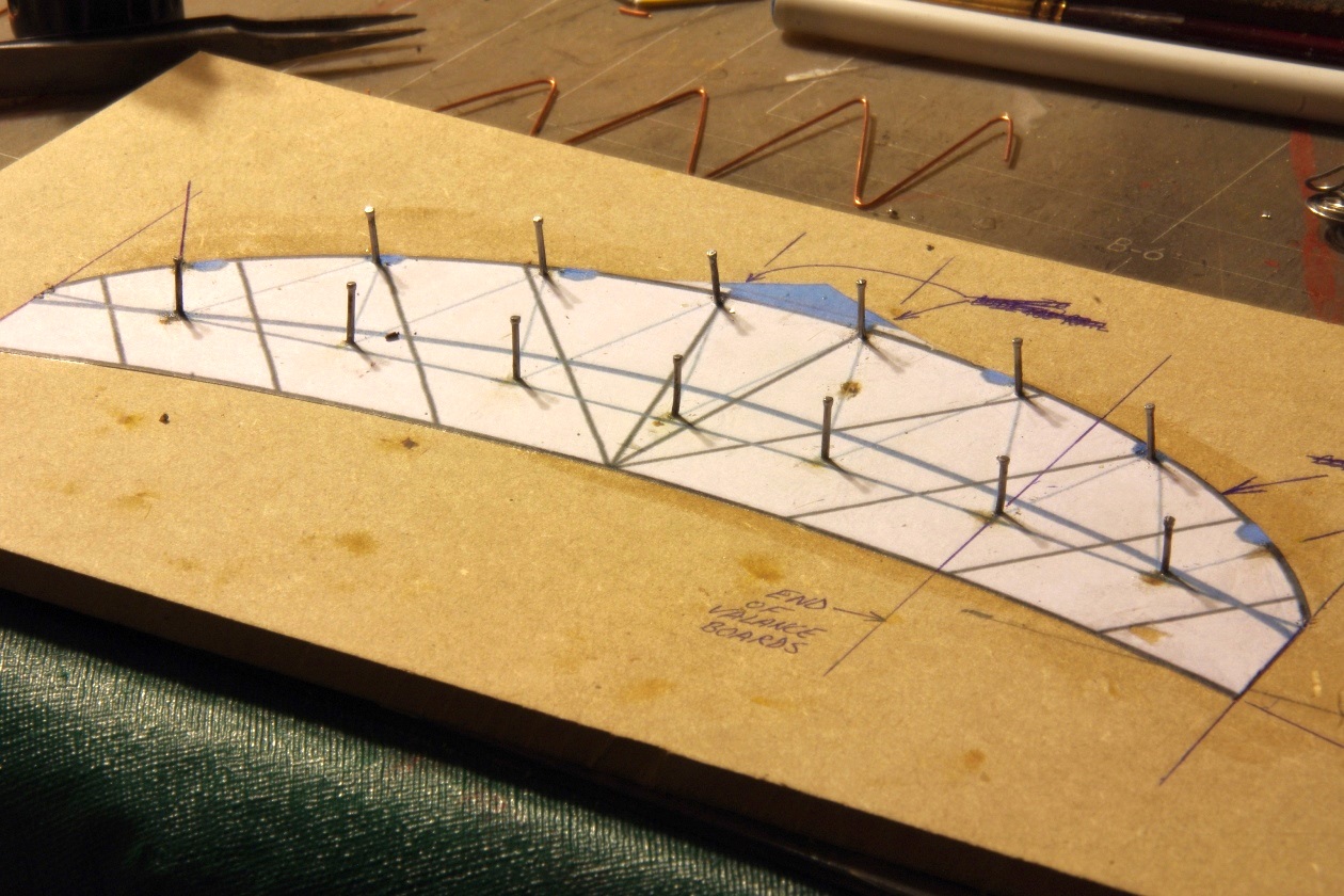
Station canopy construction. I draw a pattern using the computer and print it out, cut it to shape and glue it to a piece of timber. This forms the jig on to which I bend wire to shape around the jig to form the frames.  
Using the photos to get the right look
and arrangement of the bracing.

I drew up a pattern for the canopy frames
to suit the model dimensions.


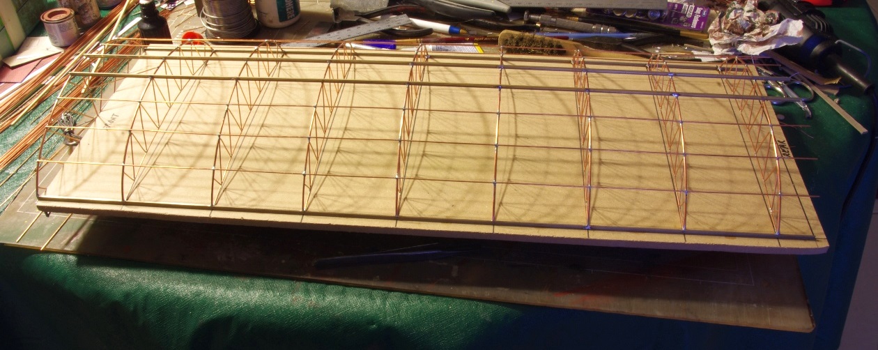
I made enough trusses for the model and made only one front end truss as it was different to all the others.

Nails to use as guides for
making the frames.
Using copper wire that has been
work hardened, the joints are
soldered to form the truss frames.
Each frame will be the same as the next.
The front most truss frame was
different in that it was deeper to
hold the timber panelling.
Only one of these was needed.
Another jig plate was made so I
could form all of the frames together
to create the canopy structure.
Canopy ready for placing on the model.
Assembly of all the trusses. Checked for fit and made a few small adjustments so it fitted into the post rails. Solder all the linking rods to make all the trusses rigid and add the top ridge vent along the whole length using three lengths of scrap Code 83 rail.

The canopy was made so that it
slipped in between the post rails.
Canopy in place and glued
in with Supa-glue


I made the end valance from 1mm match-board styrene, drilled holes in the ends, shaped the ends (bottom of the timber planks) with a needle file, drilled a hole in each plank and cut out where the telegraph wires went through......painted and weathered to match the old photos....including the part missing battens and slightly skewed last plank on the right hand end of the valance.
Styrene scribed sheet or"match-board"
valance.
Painted and weathered ready to
glue onto the end of the canopy.


The resulting model now painted and compared
to the prototype it has that distinct likeness.
The internal telegraph poles were also made
and placed on the platforms.
Even though the model is only about half the length it should be, I think
the right "look" and atmosphere has been created.

Point and signal rodding for the yard

Point & signal rodding all in.....made from copper wire and styrene, supaglued down one wire at a time. Though only static, they are essential. The wire is about 0.8mm to 1mm in diameter, and the same material was used for the bell-cranks which were just bent with a pair of long nose pliers and slightly squashed make them a little flat.

Copper wire is a very useful material
in this instance.
Each of the main points (or turnouts)
areactivated by point rodding.
The point rodding seen down along
the track on the left hand side.
Completed rodding painted and then
with weathering using powders.
The signal cabin will butt up to
the timber planking.
Something missed by many modellers is the fact that the odd diesel or railcar spills oil. Running a diluted brown/grey oil spill along the track in a straight line can add to that little extra detail to track-work.

Lower Quadrant signalling for the yard

Photo by the
late D A Colquhoun
The lower quadrants signals in the yard were in place right up until the end of the station yard's existence. I made these from the Ratio brand LNER signals kit and used some left over GWR arms from the Porthminster layout. Suitable modifications were made to give them that look that you see in the prototype photos.The arms were modified to a taper as were the arrangements of components to get the desired result. 
Using a soldering iron to "melt in"
the spring steel hand-railing I custom
make for each signal bracket.


I always add hand railing to the bracket signals not supplied in the kits. Our signals share a common heritage with the United Kingdom signalling as the majority of the early South Australian Railway signals were imported from there.
Photo by the late
Douglas A Colquhoun

Painted and ready for weathering.The 3rd shunting
signal half way up the mast is for the reverse
movements back to the running shed from the station. 
Masked up ready for spray
painting with matt black.
The yard clearance signal for main line (right arm) and
passing loop (left arm)


The yard home signal for station (left arm) and
good road access (right arm) The small shunting signal is
for access to the running shed behind the camera.

Red Hill Bridge

The Bridge itself is modelled on the old "Redhill Bridge" that straddled the rail yards carrying Grand Junction Road. The base is 6mm MDF with two slots cut in so it self locates over the hinges and doesn't move. 
The bridge deck made from 6mm MDF and girder glued into the slot cut in the centre.
The loose timber strips will be glued in to form roadside guttering.
The prototype Red Hill Bridge used to create the model.
This was an unusual structure with only a centre girder to support the two road decks either side, unlike conventional bridges with a girder on both outer sides of the road deck. 
The underside showing the rare earth magnets used to hold the bridge in place over the hinges on the abutments.
The girder is soldered tin and brass with the fencing made from styrene corrugated iron, with styrene and timber railings and posts. 
The completed removable bridge in place with an Rx Class locomotive to give
comparison of the size of this structure.
The road deck with completed guttering and weathering of road surfaces and fencing.
A couple of vehicles add to the scene, both late 1950s and early 1960s era.