SAR LMS GWR

SAR LMS GWR
SAR "Commercial Street" - LMS "Wellingford & Bakewell Bridge Railway" - GWR "Porthminster" - Port Dock Station

Monday, 14 April 2014

A Goods Shed for Penwith yard...

A large size of Goods Shed was needed for the loading track, but what to put there? Having built a Metcalfe Models red brick goods shed before for my Wellingford LMS layout, I supposed it would be a good idea to merge two together to get the six window/bay length.  Making the necessary modifications along the way to obtain a near enough looking model proved successful. The goods sheds used for reference were those of the style at Tetbury or Broadway to name a couple.
The two Metcalfe kits melded together with the office and weighbridge rooms attached at the end, all card used from the two kits. The only things added was a large sheet of Metcalfe slates for the massive roof and the upper skylights at each end. These window skylights were also typical of this design shed.
Adding the frame peices individually.
To make the skylight windows, I scanned a diagram of Tetbury Shed in a publication, scaled it to the right size for the model and printed it out on copier paper. Window panes were then individually cut out and the paper skeleton was then PVA glued to some clear shirt box lid. After fixing the windows to the model, the individual styrene frame pieces were glued in with PVA glue to complete.
The main line side of the Goods Shed with that unmistakable skylight window style.
A steel beam at each of the entrances was also added as per the design.
To finish, gutters and downpipes were strategically placed to cover joins in the card walls.

GWR water tanks & footbridge

Before painting.
This layout keeps putting up challenges. You know that saying – if you want it done, do it yourself. Not available as kits, these tanks had to be scratch built. This was the case where the water tanks were concerned. Commonly known as Brunel style tanks, I had a go at building them with a little trickery thrown in! The models mostly consisted of styrene, with the cast iron parts of the columns dressed with copper wire.  Research showed that there were many size tanks made but all had a similar styling with regard to the cast iron work. I needed one for Penwith Junction, and being  a main line station needed to be larger rather than smaller.
Applying the printed cast iron looped frames.


The difficult area was the cast iron looped frame directly under the tank. My solution was to draw up a colour image design on my PC and print it out on matte photo paper. Trimmed and glued on with a degree of weathering, it looks convincing.


While I was on the tank thing, I made up an all steel type to present to a friend who has helped me out with reference books, videos and photocopies of relevant material that I needed for the Porthminster project. He now has a nice matching set for his GWR main line station.


The tank was of the same style but with the all steel "I" beams. The two cranes are from the Ratio range, shortened slightly to sit on top of the passenger platforms, complete with fire devils. These combustion fires were used to help prevent water freezing the pipes when not in use between visiting engines during inclement weather.

Another item of purely Great Western style was the footbridge. I procured a kit from Scalelink, but I was somewhat confused by the instruction sheets and construction methods. I assembled it my way with a few modifications along the way. One being that it was to be wider than the kit instructed. Fortunately there was enough length in the etched brass lattice sheet supplied to account for this.
Also I added guttering and downpipes, plain ends to the canopy at the bottom of the steps and a few tweaks to the flimsy canopy frames to make them stronger.
Acombination  of styrene and brass works for me. Supaglue is the answer here. whatever it takes to achieve the result.


It worked out well and sits proudly across the platforms matching in with buildings as they were at Radley Station, which the buildings were modelled from.

The completed footbridge.
The layout is now starting to look more like a railway with curtains made and clipped on with press studs. A must for top presentation at Exhibitions. There is still another coat of Carriage Green to be applied around the fascia areas above the curtains.
Looking from junction end of Penwith Station.
Looking from the goods yard end of Penwith. The four doll signal gantry
sit proudly on the platform ramp. Another Scenecraft Signal box is
place opposite with accompanying point rodding and ground signals.
Till next time - good modelling!!!

The Summer Progress Report

The tunnel entrance at Penwith Junction was the first area of the layout to get the scenic treatment! The broad cutting slopes appear so typical of Brunel’s designs and quite visually effective I think.
Penwith Junction portal with a line-side hut build into the
cutting inside a retaining wall alcove.
Penwith Junction with a repainted Scenecraft
Signal Box. Signals & fencing are Ratio product.

Continuing around this end of the layout the small road bridge was clad in Slaters plasticard stone, and decorated the same as the tunnel portal. The cutting for the branch line had some rocks crafted from foam and attached with expanding foam. The entire plastered area was painted with a mid brown acrylic paint. The grasses were then added. Most of the area had Heki wild-grass matting cut into differing shapes and teased to fit around the landscape, glued on with PVA glue.
The cutting road bridge with stone walls and signal for the
Main Line to the left, Bay road to the centre and sidings
to the right. Note the strainer cable across the track.
The branch cutting that leads
to the viaduct

It was always intended to have an abandoned mine in the corner. Some more internet research resulted in a number of images of the skeletons of pump houses still standing around Cornwall. It was noted that Cornish smoke stacks were rounded whereas Welsh stacks were mostly Square. I set to work on scratchbuilding the building from thick Balsawood and clad with embossed stone plasticard. The stack was made from a cardboard roll, sliced down one side with a tapered strip removed. When the gap is then closed up by slightly twisting the tube, a tapered tube results.  With the join glued and sheathed with stone embossed plasticard suitably aligned to give the desired effect.

Pump house clad with stone, quoining added
and putty applied.

Pump house constructed
from Balsawood.
The corners of the building were then dressed with quoining cut from paper. All gaps and edges were then wiped with modelling putty using my finger tip. Once dry the model was painted with grey primer enamel. Then a thin wash of cream enamel, a dry brushing of brown highlighted the stone work. Finally the whole building was then dusted with weathering powders to age the surfaces. On the north side of the build some green was added to represent moss. Red brick papar then covers the upper cap and rim.


Completed stone work with
weathering - ready
for the red brick top to be applied
with strips of brick paper
three courses at a time.


The old tin mine site with settling tank
and out buildings. The yellow and
violet heather compliments the scene.
The access road is overgrown leading
down from the road bridge.


The viaduct has had some attention too. Flywire was arranged around the bottom of the piers and profiled with lumps of screwed up newspaper. This area is currently under construction. While the viaduct is the only railway object on this part of the layout, its demand on the scenery is huge, and integrating it into the scene is quite challenging to say the least!

Monday, 2 December 2013

Getting a bit plastered!

Having done some more testing on the track, I was happy to start the plaster work over the aluminium flywire to form the hills and landscape. The basic system used here starts with strips of Balsawood (12mm square section cut from sheets) glued just under the edge of the profiled fascia boards. Flywire is then stapled to the Balsawood and the baseboards along the track edges.  Scrunched up newspaper then supports the flywire and also keeps drips of plaster from landing on any hidden track. Plastering is done using Cornice Cement, a much better product than any other plasters due to it having greater adhesive quality and is much harder than the average plaster. Due to its hardness, there is only one layer needed over the flywire instead of two, saving time! When all is dry, the newspaper is removed from underneath.
Plastered module with the branch line cutting formed,
the viaduct being directly to the right of this view.


The profile boards then get their first coat of acrylic paint which will be the final colour for presentation of the layout. The paint is brought up over the edge where it meets the plaster. This does two things; it helps harden the edges further, reducing the chance of chipping and if in future any grass scatter gets accidentally rubbed off the edge, it won’t be obvious.
Penwith Junction with the Porthminster branch off to the upper left.
The profile fascias are given their first coat of paint 
The back board behind the viaduct has been applied with a photographic backscene of” Llanberis”, a welsh mountain scene printed on a premium paper which has a waterproof plastic backing. Applied using spray contact adhesive, it went on beautifully and am pleased with the result. The plaster work will then meet the bottom edge of the photograph.
Brunel Viaduct with rear back scene installed and
flywire stapled in ready for plastering.
Till next time, Merry Christmas!

Friday, 22 November 2013

"Commercial Street" - 1960s South Australian Railways

Here is a unique hinged baseboard idea that many English modellers had developed many decades ago of modelling a fold up railway known as the Minories. This idea consisted of a terminus station at one end and a specially set out track design at the other end. At the Terminus Station, which usually had high surrounding walls each side of the whole station, a road bridge straddled the station platforms concealing a pair of hinges. This allowed the two baseboards to be folded over on each other for transport or storage. To make the terminus operable, a fiddle yard would then be attached at the station throat concealed under another road bridge leading into a hidden fiddle yard, which would be bolted on to the Minories. I proposed the idea that if the fiddle yard could be permanently attached to the station throat via another set of hinges, the whole layout would fold up on itself without having separate baseboards, extra sets of legs and no track alignment worries. Having tried the idea, and making use of a large warehouse building as a means of hiding the fiddle yard, and using block sections at the end of each siding, a successful scheme would allow the operator to run trains from the terminus to the fiddle yard and back without touching/handling any engines or rolling stock. Under-track magnets would be located at appropriate positions around the layout to allow hands free shunting using Kadee couplers.


An industrial theme would be appropriate for there were dozens of sidings in and around Port Adelaide and the Port Line in South Australia. Small industrial sidings were everywhere, built in and around roadways, sometimes in the roadways. Roads that ran over the railway with girder bridges or embankments with simple concrete bridges such as those at Mile End or Port Adelaide look visually interesting, and in this case used to hide the hinges on the baseboard. Small passenger stations such as Grange or Semaphore were built immediately next to a roadway and have simpleness to them. Of my own design, “Commercial Street” allows one to run Goods and Passenger trains and have the illusion that the trains have come from and go to a main destination hidden by the warehouse (the fiddle yard). Due to the shortness of the sidings and the use of small radius points, an impressive number of wagons and engines can be accommodated on the layout without being overcrowded.
The fold up layout before point levers
mounted and ready for scenery.
After scenery work.

The removable road deck held in place
by magnets.

The road deck in place.
Even on a small layout like this there is comfortable room for five locomotives, twenty wagons (mostly 4 wheelers), two brake vans and two passenger cars or a pair of railcars.
The layout stands at 1 metre high so when sitting on a standard chair the scene before you is just under eye height. This gives the operator a sense of being in the scene.
The Co-operative  and woodyard
sidings
A 930 Class shunts in an open wagon for 44 gallon drum pick ups
and an oil tank for the depot storage tank fill.
The road bridge across the face of the
warehouse to disguise the fact that
there hidden sidings.
The warehouse with on street wagon loading and unloading.


The warehouse was made from two Metcalfe Warehouse card kits, kit-bashed to obtain a very close match to the old Woodsons building in Port Adelaide.
The engineering workshops with loading gantry. Even though the building is between you and the siding, it still has that atmosphere that a modeller craves due to the quirky nature of the track and road alignment.
An Rx Class 4-6-0 shunts in two
open wagons for an outgoing
consignment to a customer!


A 500 Class shunter at the road crossing at Commercial Street pushes
in a load of cut logs into the woodyard.
Cameo scenes play a big part in creating atmosphere in such a small area. Great pleasure was had creating this piece as I strive for realism.
The hidden sidings inside
the warehouse.
The driver of the P Class 2-4-0 checks the road as he pushes into
the warehaouse sidings under the bridge.

A 700 Class pulls into Commercial Street with a local passenger.

All the locomotives and most of the rollingstock are scratchbuilt with exception of the Rx class which is a brass kit and the 930 class, a Trainorama loco with sound fitted. The layout is DC.

Progress with Porthminster

During the course of winter I had to take a break from Porthminster to build a small fold-up South Australian Railways layout for a presentation I had to give at a Convention in September. (See left hand photo at top of this page - a post on that layout will be forthcoming). Once that was out the way, I constructed the platforms at Porthminster and Penwith stations. Construction was somewhat challenging with curved platform faces and very few straight edges.
All track ware then wired to four operating panels, one at Porthminster, the branch terminus, one at the hidden sidings, one at Penwith Junction right behind the Bay roads of the branch, and one at the main goods yard at Penwith Station. The plan is to have three operators (or four if needed) to operate the layout at exhibitions. Some tricky wiring with assisting relays aided the switching of the diamond crossing and single slip at Penwith Junction, and the scissors crossing. I also installed a four speaker digital sound system to pipe steam train sounds around the layout.
Once thoroughly tested, the layout was pulled down and the modules were taken outside the house so the track could be painted. A light rust colour for the rails was first applied (at 45 degrees to the track to cover the sides of the rails) then Rail Sleeper Brown was sprayed over the top (at 90 degrees) to cover the sleepers which were over-sprayed with the Rust.
the track having been spray painted was ready for ballasting. The masking
tape around the platform faces to protect them was removed just prior to ballasting.
Some thoughts into where the point rodding would go were needed. Positioning between tracks needed to be sorted out so rows of foundations could be glued in before ballasting.
Point rodding supports glued in and painted before ballasting.
Ballasting then commenced with the layout set up again. I installed separators (20thou plasticard) between the modules to prevent them sticking together when the ballast glue was applied. The standard mix of PVA glue and water was used after applying a spray of water and detergent.
The plastic separators needed to stop the modules from being stuck together.
With all the ballasting done, the rails were cleaned up and more testing was needed to clear any faults with point motor operations or bits of ballast in frogs and checkrails. A few showed up where the blades had stuck, but were easily remedied with the application of water and some cleaning up.
Penwith Junction freshly ballasted just before gluing.
In October I attended a national convention of the British Railway Modellers Association during which there was a modelling completion. I entered the two station buildings I had scratchbuilt for Penwith Station for the Lineside Structures Trophy. Winning the trophy was a bonus and was the icing on the cake for a good weekend away! The prototype I chose was Radley Station, which fit nicely into the platform arrangement I designed for Penwith. Radley Station also had a nice covered footbridge linking the two platforms and there will be one made to fit the same arrangement in Penwith.
The Main and Island platform buildings for Penwith. The footbridge will be
placed at the near end of the buildings.
The two tunnel portals have now been painted and weathered, glued into position to allow scenery landscaping to get under way.
The Penwith Junction portal painted and weathered. Inside the entrance there is stone walling
extending about 200mm inwards. Flywire with newspaper support is ready for plastering.
 A parting scene for this post is the 517 Class hauling a couple of four wheeled coaches through the scissors. Penwith Signal Box sits in the end of the platform with the four doll bracket signal sitting proudly opposite!
TO BE CONTINUED!

Friday, 21 June 2013

Porthminster Modules & Track

Construction of the modules proved to be more difficult than first thought due to the shapes needed to produce each module. There are so few straight lines in the plan that each module is different from the next physically in shape and depth.  There seemed like mountains of scrap timber left over due to the immense number of jigsaw cuts needed to produce the curved track beds and profile boards.  The first module constructed was the end module with the tin mine.  The two bridge modules were made up without the semi-hidden main line storage loops. Then the two Penwith Station modules were constructed keeping in mind that there was no room for slip ups in their dimensions so that when the last module was constructed that they all meet up without alignment issues.
The layout viewed from the branch junction end. All track work complete.
Operators will be in the central isle while public viewing around the outside.
Once the modules were set up and all clamped together, all the joins were drilled for two alignment dowels and two (3/8”W X 2 ½”) bolts with wing nuts. Each module has its own fold down legs with gas struts attached. These will hold the legs in place during assembly/disassembly allowing a speedy set up and pull down time. The main timber frame of each module comprises mainly Pine of 63 X 19mm cross section. All the baseboard tops and track beds are 6mm MDF. All the profile boards are 3mm MDF. The last part of the plan was to arrange and construct the semi-hidden storage loop timberwork behind the view block of the bridge modules. Some very tricky woodwork was needed here.
Looking along the backdrop with the viaduct to the left
(front of the layout) and the semi-hidden passing
loops for the two main lines.
The reason this layout is being built is due to the acquisition of that beautiful Brunel Viaduct. So it was carefully removed from the cut out layout pieces in which it was built on and arranged on the new modules. On the original layout the last owner had built the viaduct as one piece, but was thankfully only resting, not glued to the piers. The viaduct was trimmed to 3m from the original 4.5m. Some juggling of the deck was needed to allow future cuts to be made at the joins of the modules so that none of the fans would be in the way.   Each pier was trimmed to length so the timber fans and deck would be level. The deck was then aligned to the track plan and clamped. All the piers (cast from plaster with a timber core) were then glued and screwed from underneath to ensure a solid foundation to finally glue the deck to. Once all the glue had dried, cuts were gingerly made at the joins of the modules – a tedious task keeping in mind I didn't want to destroy any of the timber guard railings along the deck. Though the viaduct was laid with code 100 track, ballasted and glued in the 1960s, it was in remarkably good condition so I consciously decided to leave it unmolested and marry it to my code 70 Peco track at either end.
The The Class B Brunel Viaduct with Class A stylised piers originally
built by Kev Loughhead in 1969 for his Moping Branch Railway 

Click on the photos to enlarge

Always seeking a challenge, the tracklaying was begun with difficult areas tackled first. The scissors situated in the middle of Penwith Station yard was made up using four Peco medium radius points and the short crossing. Careful trimming allowed for all the components to be superglued together producing a very unique piece pleasing to the eye.
The five Peco track components needed to produce the scissors for Penwith 


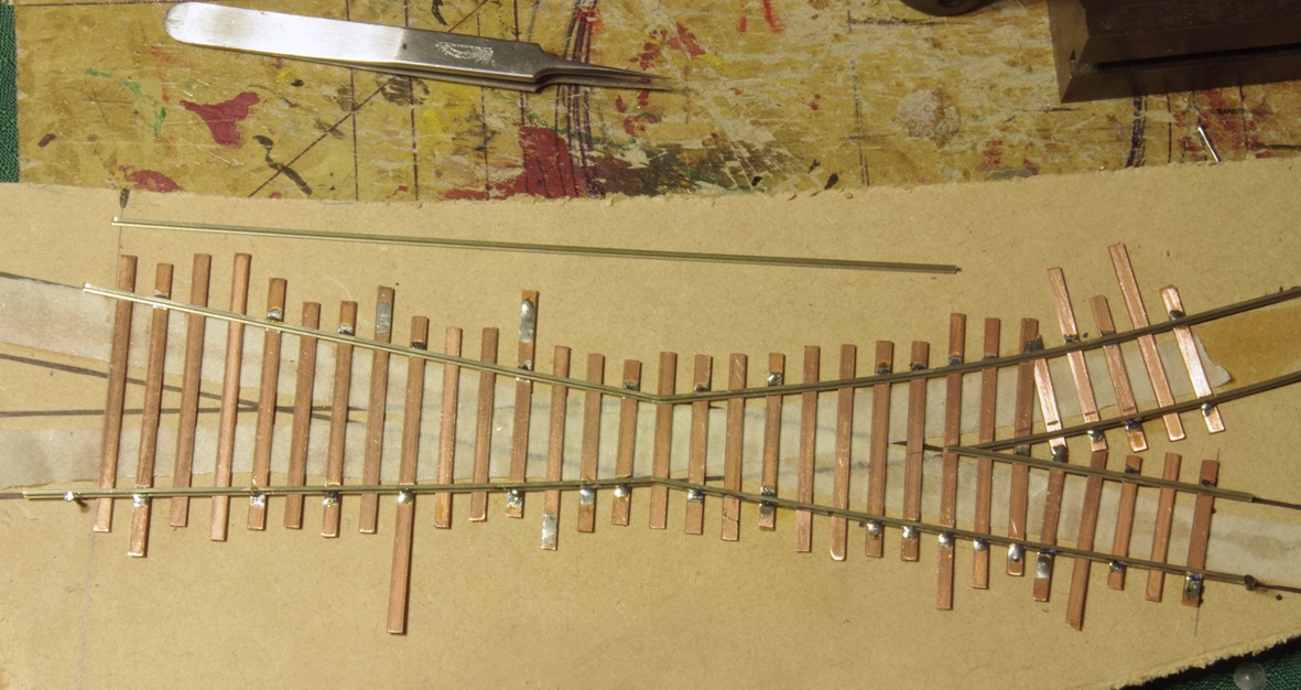
As I was nearing completion of the track work for the branchline junction in Penwith I had no choice but to hand make the double curve crossing. To get a smooth transition of curves and to get the curved points to fit, the crossing needed the curve of the branchline to start on the diamond rather than after it. I was quite happy with the result and running different types of vehicles through the crossing showed up a few adjustments needed for smooth running.
The double curved diamond crossing under construction.
The crossing in place.