


Then a hole of 4mm for wires drilled on an angle to enter just under the baseboard.
 |
| The three wires for each turnout pass through the front frame. Also the actuating wires are seen poking out as well. |
I bent up the 1.5mm spring steel wire into “V” shape, added a plastic guide made from 20thou styrene and Evergreen™ hollow 3mm square rod. The guide holds the rod in place and stops it falling out of the point tie bar. The "V" acts as the "take up" for the longer travel of the slide switch. Once all the point rods were done the switch panel was installed.


The switch panel was marked out with the position of each slide switch. 30mm x 11mm Pine was used for the panel. The shaded area was then cut out.

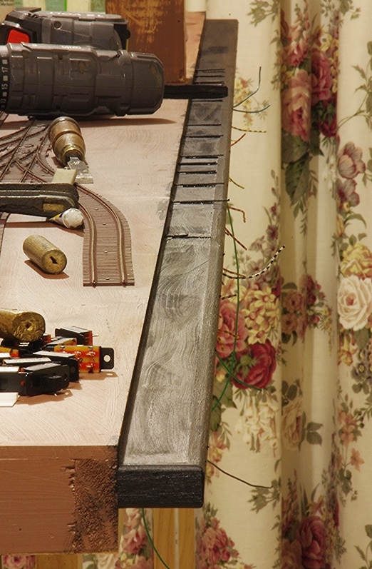
The Pine panel needs to be PVA glued to the frame 2mm below the 6mm MDF baseboard all the way along using long nails, so I pre-drilled the panel before nailing to prevent the pine splitting.


The front switch panel which runs the entire length of the three modules is 30 x 11mm Pine with the slots cut in to accept the switches when completed, and was held in place with pre-drilled long slim nails.
The Tasmanian Oak (but any hard wood will do with a “D” shape profile) rail was then added along the outside. This forms the holes for the slide switches. The front ledge was painted black so I could fit the switches the next day. Electrical wires were then soldered between all of the turnout frogs and wing rails to their respective switches.

The actuating rods needed to be trimmed with side cutters, then bent to 90 degrees and slid into a hole drilled into the centre of the slide switch close to the plate. Two small screws then hold the switches in position.
 |
| The slide switches wired to their respective turnouts. These are double pole double throw switches and only one set of poles were used. |
No comments:
Post a Comment