SAR LMS GWR

SAR LMS GWR
SAR "Commercial Street" - LMS "Wellingford & Bakewell Bridge Railway" - GWR "Porthminster" - Port Dock Station

Wednesday, 12 August 2015

Turnout mechanism and Slide Switch install

Time to prepare for the point switches. Each point position was marked out with a white line along the edge of the baseboards, a 1.8mm hole drilled for the actuating rod right where the line is and within that 2mm space you see just below the 2mm MDF baseboard. 1.2 to 1.5mm spring steel wire is used for the actuating rod.


 Then a hole of 4mm for wires drilled on an angle to enter just under the baseboard.


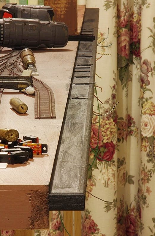
The three wires for each turnout pass through the front frame.
Also the actuating wires are seen poking out as well.

I bent up the 1.5mm spring steel wire into “V” shape, added a plastic guide made from 20thou styrene and Evergreen™ hollow 3mm square rod. The guide holds the rod in place and stops it falling out of the point tie bar. The "V" acts as the "take up" for the longer travel of the slide switch. Once all the point rods were done the switch panel was installed.


The switch panel was marked out with the position of each slide switch. 30mm x 11mm Pine was used for the panel. The shaded area was then cut out.


The Pine panel needs to be PVA glued to the frame 2mm below the 6mm MDF baseboard all the way along using long nails, so I pre-drilled the panel before nailing to prevent the pine splitting.


The front switch panel which runs the entire length of the three modules is 30 x 11mm Pine with the slots cut in to accept the switches when completed, and was held in place with pre-drilled long slim nails.


The Tasmanian Oak (but any hard wood will do with a “D” shape profile) rail was then added along the outside. This forms the holes for the slide switches. The front ledge was painted black so I could fit the switches the next day. Electrical wires were then soldered between all of the turnout frogs and wing rails to their respective switches. 


The actuating rods needed to be trimmed with side cutters, then bent to 90 degrees and slid into a hole drilled into the centre of the slide switch close to the plate. Two small screws then hold the switches in position.
The slide switches wired to their respective
turnouts. These are double pole double throw
switches and only one set of poles were used.

Wednesday, 22 July 2015

Concrete floors for Port Dock

Common in the construction of railway locomotive service facilities was the use of ash pits for collecting ash, but also access to brake gear and mechanical ash-pan servicing. At Port Dock there used to a "running shed" or locomotive depot that was used to store and maintain a local locomotive fleet for use around the yard and in the port area in general. Duties included local goods shunting, pilot duties for the station and goods movements up to the nearby Gillman Yard, but locomotives were often used to deliver and collect goods from Dry Creek further away. On my model, I wanted to have that capacity to receive and dispatch goods to and from Commercial Street, which in essence are trains to and from Adelaide or Mile End goods yard. Port Dock had all the connecting lines to the local area from Adelaide and was quite extensive. The running shed had ash pits just outside the front of the shed. The four road shed was a simple rectangular shape with a small workshop off to the side.
The running sheds at Port Dock. Photo taken by Douglas A Colquhoun.
The two ash pits were on the two central roads.
  
The ash pits.
The running shed floor.


The ash pits and the floor for the 4 road running shed. Balsa-wood was used between the tracks and on the sleepers to build up the height to about 1.5mm from the top of the rails, then 1mm plasticard was layered over the top. This leaves about 0.5mm clear of the rail head so cleaning of the rails isn't made difficult. Then the joins and cracks were scribed into the surface ready for painting and weathering. Weathering powders were used to highlight the scribed lines and give that dirty concrete floor effect.
The styrene is then painted with "concrete" enamel - two coats let to dry then powders used to get that grimy look.
I used an "Exacto" knife to scratch in the lines, but instead of using the sharp edge, use the blunt edge (use it
upside down), run lines at random connecting the tooled cement lines (which were also done the same way)
Ash pits completed with the pits made by building up depth using balsawood strips glued under
the baseboard to create the rectangle pit sides and ends. Then a piece of styrene added for the floor.
A set of steps at one end in each pit are yet to be installed.
The ballast will be filled in around these floors to "bed" them in to the flat ballast and dirt filled surface required. Till next - happy modelling...!

Tuesday, 21 July 2015

PORT DOCK STATION project

Its winter here in southern Australia (June, July & August), and a good chance for some modelling to while away those "too cold to go out" times. I decided to make another fold up layout companion for Commercial Street. The same size yet it would complement Commercial Street with trains to and from a terminus. In the port of Adelaide in South Australia, there used to be a terminus, now gone and nothing remains of the site. Now it is a police station, car park and a railway museum. My design is a very much condensed but I think quite interesting plan to run passenger and goods trains from and to Commercial Street, along with somewhere to store (and lets face it - show off ) one's locomotive fleet.
The connection to Commercial Street is at the top right hand end of the drawing.
Few photos are available of the old station, originally called Port Adelaide but later in life was renamed Port Dock.
My research collected this photo taken by D. Castle in 1955. The station looking rather derelict here but will make an interesting feature on the layout. The canopy and station building were demolished in 1963. The platforms were kept and an "Art Deco" style building was erected in its place. My model will replicate this era of the late 1950's An old "Red Hen" railcar set sits in the station.
The original station building that I want to make a model of, with its
painted stone work and red brick quoining. A quite handsome
building, attached to the end of the barrel roof canopy.
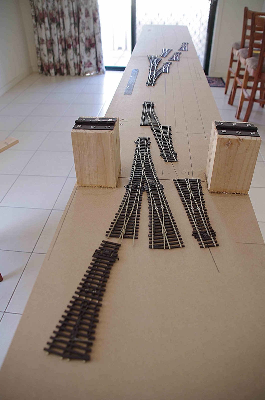
The basic fold up baseboards shown here
with the turnouts laid out to see if its going
to work off the drawing.
Some tweaking of the placement of the tracks was needed but essentially it laid out like the drawing and would work. The hinges which will be hidden under a lift off bridge are seen here.

Shown here the two fold up layouts are
connected to see if the track will
line up from Commercial Street.


Once happy that it would work, then track laying commenced with PECO code 75, the same as on Commercial Street. The track coming through the opening at the end of Commercial Street needed a slight realignment to match up so a short section of about 100mm of track needed lifting out. Having laid all the track I had completely forgotten to install the under track magnets for shunting. I use Kadee Couplers on everything so the strategic location of magnets makes shunting a real enjoyable experience. Hands free operation of shunting movements keeps things a little more real for me.

The join between the old and new
baseboards with the
small re-alignment.
The two magnets seen here with both
Kadees activated.
I use two button battery sized rare earth magnets as uncouplers. I drill two 10mm blind holes, place in the magnets attracting each other and lay the track directly over the top.


A reground 10mm drill bit is used to drill two blind holes
 just deep enough to accept the magnets. They don't need to
be glued in if the drill size is a neat fit for them.


The 10mm drill was ground to an almost flat profile. This was done to stop the drill from grabbing the timber as it drills through. Its far more predictable than a standard profile drill bit which can grab without notice.

The two magnets side by
side - attracting each other,
NOT REPELLING


The completed installation - very quick and easy.
I usually mark the magnet's position with either a small
post or a painted mark on the side of the rails after
the ballast is done.


The magnets are 10mm diameter and 3mm thick......

Next post I'll discuss the Locomotive shed floor and ash pit construction. A task that is made easier before ballasting. Till then - happy modelling!

A ballast train visits.......

My Commercial Street layout has had a tremendous reception in recent times and many hours have been spent shunting the layout by friends and colleagues. Some less than usual trains have visited and a couple of specials were on the roster.

One sunny afternoon a SAR 500 Class deisel is spotted bringing in a rake of Z hoppers.
The train eases into the main yard past the Cold Stores

On another day, a special historical society tour special arrived...! This 500 Class model locomotive No.504 was scratchbuilt from a myriad of materials, has a brass chassis and driven via a pair of universals through the cab from the tender. The motor has two flywheels on it, and provides for nice smooth running capabilities.

South Australian Railways 500B Class number 504 "Tom Barr Smith" arrives with  Dining Car "Adelaide"
The big 4-8-4 pulls over the crossing to run around the train. The guard stands his
ground with a stop  sign. This was a common occurrence up until
the 1980s on the railways here.
Some assistance was needed as the train was too long
for the run around loop. So diesel shunter No.500 pushed
the consist up to allow the 504 to back on to its train.
504 is ready to leave. An ex Overland wooden "E" Class car
and a 500 Class steel car make up the consist.

Friday, 19 June 2015

Great Moor Street - Minories

Great Moor Street in OO scale in all its old world splendour.
An overview of the station canopies. An Ex Midland Flatiron 0-6-2T waits in
Platform 3 with some Ex LNWR stock.
As a lad of a young age I looked starry eyed at a unique hinged baseboard idea that I had seen in my edition of “The Railway Modeller Book of 60 plans for Small Locations”. I would like to build that one day….the time had come and so it was done. This fold up railway using a space of 7ft x 1tf in size was known as the “Minories”. Consisting of a terminus station at one end and a specially set out track design at the other end, it offered train operations like no other. It was a signature piece by CJ Freezer no less, and learning over the years that his designs were held in high regard, I give it a go. The terminus station has the high surrounding walls each side of the whole station and a road bridge straddling the station platforms concealing a pair of hinges. This allows the two baseboards to be folded over on each other for transport or storage. To make the terminus operable, a fiddle yard would then be attached at the station throat concealed under another road bridge leading into a hidden fiddle yard, which would be bolted on to the Minories.
A view under the canopies of Great Moor Street. I think this photo captures the
right atmosphere which was what I was striving for here, that maze of frames
and elegant styling of the steam days.
My thoughts were to have a fiddle yard that was permanently attached to the station throat via another set of hinges; the whole layout would fold up on itself without having separate baseboards. Making use of a large warehouse building as a means of hiding the fiddle yard, and using block sections at the end of each siding, this allows the operator to run trains from the terminus to the fiddle yard and back without touching/handling any engines or rolling stock. Under-track magnets would be located at appropriate positions around the layout to allow hands free shunting using Kadee couplers.
The layout plan which shows the three 1065mm modules that fold over
each other - all permanently fixed together with hinges.
The view of the coal staithes and signal box. All the points are switched
using a simple push-rod system attached to a slide switch which changes the
polarity of the attached point. The mini control panel can just be seen
below the front ledge.
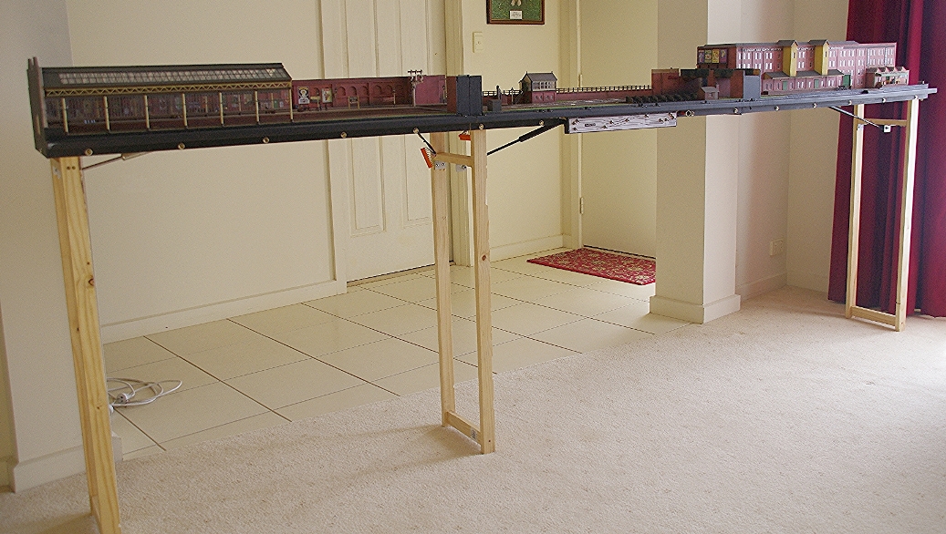
Timber baseboards were made using 6mm MDF fixed to 42 x 19mm pine frames, with 6mm MDF used for the station end and side walls, warehouse walls and road bridges. Self-supporting legs extend from under each baseboard section and are kept open using gas struts. This makes for very rapid erecting and knockdown of the layout. The warehouse takes its cues from the Ex Midland Railway Sandon & Canada Dock Goods station.
A view of the lift off bridge that covers the hinges fixed on either side on top
of the abutments. The bus on the bridge is of a local bus line with
"Plodder Lane" written on the destination boards - appropriate for the area.
Two Metcalfe Models Warehouse Kits were grafted together with scratch built hoist towers to achieve the result. The terminus was modelled on the Ex LNWR Bolton Great Moor Street station in Greater Manchester. A number of images exist on the World Wide Web and so I collected them as reference for scratchbuilding the station with its red brick architecture. The station canopy was scratch built from copper wire, basswood and styrene, with 1.5mm acrylic sheet used to represent the glass roofing and side wall panels. Each of the trusses in the canopy were made on a jig with soldered copper wire. This ensured each truss was the same as the next. Station walls with their arched panel design were made from balsawood covered with Metcalfe Models brick paper. The signal Box was a Metcalfe Models Kit suitably re-detailed to more faithfully represent the standard LNWR design. Platforms are adorned with Ratio Kit LNWR signals, Dapol book stalls and Langley Models kit built gas lamps. Mikes Models LNWR water columns and scratch built coal staithes stand opposite the signal box.
A 4F enters station throat from the hidden sidings, heading for the goods
road in the station to be reversed into the sidings after the 0-8-4T has
completed its shunting moves. The water tank structure is removable to enable
the canopies to clear that area when the layout is folded up.
The large warehouse hides the four storage roads. The wagon turntable is located on the piece of baseboard
that sticks further out. The furniture factory siding comes right to the end of the layout.
Wagon turntables were a common sight in and around many large goods sheds, so I incorporated one along the front sidings of the warehouse. I used an Atlas Track 90 degree crossover cut down to size and secured with a central pivot screw. It sits in a scribed balsawood deck surround which represents the timber planking commonly used to cover the drive mechanisms for the capstan rope tow system. Although the turntable is for static appearance only, it gives the scene purpose and access to the furniture company siding at the end.
For more photos, a Plan of the Month feature was published in the April 2015 edition of Railway Modeller of Great Moor Street.


The layout folded up and placed in the back seat of my car
ready for transport to a convention. Seat belts are used to restrain
in case of an accident.
This shot shows the layout semi-folded. The two station modules are folded on top of each other 
with the hinges in the bridge abutments (at floor level) and the warehouse hidden sidings module hinged
at the throat of the station (seen at the top) The sets of legs are hinged and fold into each module and are
held open by gas struts. This makes for very fast erecting and folding up times.  All the legs, power supply,
on board sound system and control panel are permanently fixed so the whole layout is self contained.
This shot shows the layout erected before adding the curtains and
rolling-stock. The control panel can be seen in the centre.
A side on view looking under the side glazed wall of the canopies.

Friday, 13 June 2014

My future Virginian Railway

I have decided to build a model switching layout based on the Virginian Railway. Details to come!
A Proto 2000 model of a USE Class for the VGN.

Wellingford & Bakewell Bridge Railway - Plan

At the recent Adelaide Model Railway Show 2014, I was asked a number of times from members of the public weather I had a drawing of my LMS layout I had on display. I didn't have any copies available so here is the plan of the layout for those I indicated for reference to this blog.

Wellingford & Bakewell Bridge Railway 
I will add some more photos later. There are a number of YouTube clips of the layout available if you search. I would recommend this clip done by a good friend of mine.

The photos below are of two stations, Wellingford, a name of my own making and modelled in the LMS style. Bakewell Bridge is modelled closely on Bakewell with a few enhancements to fit the scene.

A local goods comes off the branch into Wellingford
while a coal train waits patiently.
Bakewell Bridge Station - an adaptation
of Bakewell Station in Derbyshire in the Midlands.